
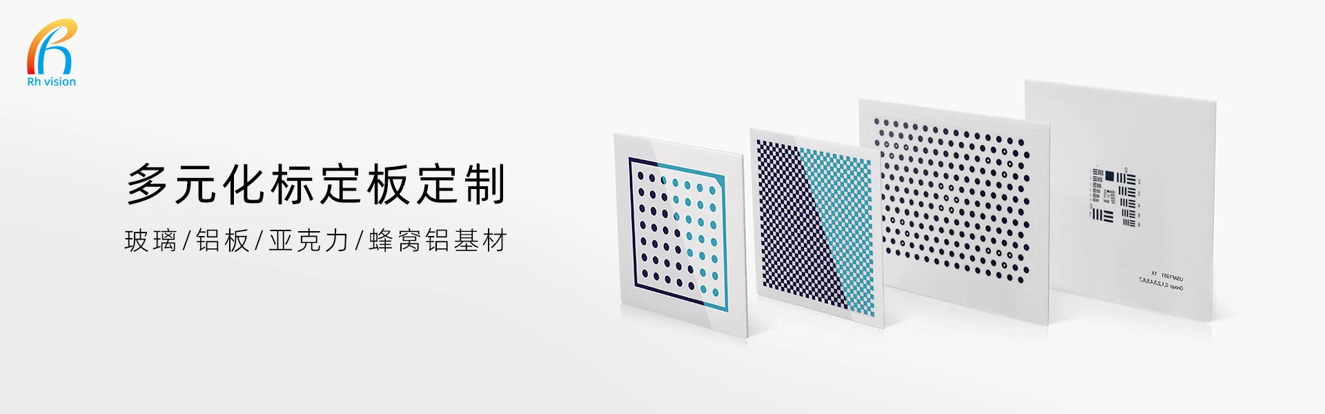
Calibration targets

Custom machine-vision calibration targets

Checkerboard, circle-grid, and coded patterns on glass, ceramic, aluminum, and film substrates — built to drawing. Pattern and accuracy inputs are confirmed against your field of view and calibration algorithm.

Pattern types

Calibration targets we manufacture

These are our published product directions. Spacing, dot diameter, coding dictionary, and active area are confirmed against your calibration algorithm and field of view before plate-making.

Checkerboard calibration target

Uniform black-and-white squares establish the relationship between image pixels and spatial coordinates, used for camera calibration and imaging-deviation correction.

Materials open to discussion
Optical glass / Ceramic / Aluminum substrate / Film
Typical applications
Camera intrinsic/extrinsic calibration; Lens distortion correction
Request a quote

Circle-grid (dot) calibration target

A regular dot array supports coordinate calibration of industrial cameras, lens distortion correction, and vision measurement.

Materials open to discussion
Optical glass / Ceramic / Aluminum substrate / Film
Typical applications
Monocular and stereo calibration; Hand-eye calibration
Request a quote

Coded (ArUco/QR) calibration target

Distinguishable coded patterns support pose recognition, partial-visibility calibration, and coordinate positioning.

Materials open to discussion
Optical glass / Ceramic / Film
Typical applications
Industrial camera calibration; Automated line positioning
Request a quote

3D-scanning and dedicated calibration target

Custom calibration patterns and substrates tailored to the field of view, algorithm, and working space of 3D scanning and other dedicated equipment.

Materials open to discussion
Optical glass / Ceramic / Custom substrate
Typical applications
Dedicated scanner calibration; 3D-scanning distortion correction
Request a quote

Stereo (binocular) calibration target

For synchronized two-camera calibration, helping correct lens distortion and determine the relative pose of a stereo system.

Materials open to discussion
Optical glass / Ceramic / Aluminum substrate / Film
Typical applications
Stereo range finding; Robot vision positioning and picking
Request a quote

Polyhedral (3D-angle) calibration target

A multi-faceted 3D structure establishes multi-angle field-of-view relationships for multi-camera joint calibration and robot 3D-vision setup.

Materials open to discussion
Optical glass / Ceramic / Custom structural parts
Typical applications
Multi-camera joint calibration; Multi-angle field-of-view calibration
Request a quote

Freeform (non-planar) calibration target

Non-planar calibration patterns custom-made for curved, cylindrical, and special workstations, confirmed by the equipment field of view, pose, and mounting space.

Materials open to discussion
Optical glass / Ceramic / Custom structural parts
Typical applications
Curved-equipment and special-station calibration; Cylindrical and rotational-body vision calibration
Request a quote

Large-format coded calibration target

A coded-pattern calibration target for large-field machine vision, 3D scanning, and dedicated measurement stations, customizable with a support structure and on-site space.

Materials open to discussion
Substrate confirmed per project / Custom support structure
Typical applications
Large-workpiece 3D scanning; Multi-camera joint calibration
Request a quote

How to choose

Four inputs that decide the target

A calibration target is not chosen by maximizing accuracy. It is derived from the camera, the algorithm, and the environment. Working in this order cuts down on back-and-forth.

  1. 01 Start from camera and field of view

    Sensor resolution, focal length, and working distance set the active area and pattern density. A larger field of view generally calls for a larger board and coarser spacing.

  2. 02 Then fix the pattern type

    Checkerboards suit most single-camera routines. Circle grids help where sub-pixel centroid fitting matters. Coded patterns handle partial occlusion and pose recognition. The pattern has to match your calibration algorithm.

  3. 03 Choose the substrate for the environment

    Glass holds flatness for higher-accuracy work. Ceramic scatters light and wipes clean, which helps under bright illumination. Aluminum takes knocks on the line. Film is light and low-cost for large formats or trials.

  4. 04 Confirm accuracy and delivery

    Spacing tolerance, pattern position accuracy, and board flatness are confirmed against your operating conditions. Quantity, packaging, and lead time are settled in the same technical confirmation sheet.

Before you ask

What to include in your enquiry

With these details we can go straight to plan confirmation. If you do not have all of them yet, contact us anyway and our engineers will work backwards from the application.

Request a quote
  • Pattern type: checkerboard / circle grid / coded / other
  • Active area and overall board dimensions
  • Cell size, or dot diameter and spacing
  • Substrate: glass / ceramic / aluminum / film
  • Camera resolution, focal length, working distance
  • Operating environment: production line / lab / outdoor
  • Quantity and target lead time

FAQ

Calibration target questions

Checkerboard or circle grid — which should we use?

It depends on your calibration algorithm. Checkerboard corner detection is mature and supported by default in most calibration libraries. Circle grids allow sub-pixel centroid fitting, which tends to hold up better when the pattern is slightly defocused or you need a more stable center estimate. Match it to your existing pipeline rather than picking whichever sounds more accurate.

How do glass, ceramic, aluminum, and film substrates differ?

Glass keeps flatness stable and suits higher-accuracy calibration. Ceramic gives a diffuse surface that avoids specular hotspots under strong lighting. Aluminum resists impact for long-term production use. Film is light and low-cost, which fits large formats or proof-of-concept stages. The right choice follows from your accuracy requirement and operating environment.

Can you build a non-standard target to our drawing?

Yes. Send the drawing or pattern file, the active area, substrate, and accuracy requirement, and we can assess it. Irregular outlines, through-holes, mounting datums, and coded dictionaries are all open to discussion; the resulting parameters are fixed in the technical confirmation sheet.

What about large-format targets?

Large fields of view and 3D scanning often need bigger boards. Options worth discussing include segmented tiling, film substrates to cut weight, and added framing for rigidity. Maximum board size and the tiling approach depend on how the target mounts on your equipment.

The notes above are selection guidance. Final dimensions, accuracy, and delivery terms are governed by the technical confirmation sheet.

Send us the drawing, dimensions, and application

We will confirm a workable plan based on the pattern, substrate, accuracy, and operating environment. All parameters are subject to the final technical confirmation sheet.